Label Switched Multicast -- An Introduction
There are two common methods for transporting multicast packets within an MPLS-based Layer 3 VPN:
- Generic Routing Encapsulation (GRE) with Protocol Independent Multicast (PIM) (also known as "draft-rosen")
- Label Switched Multicast (LSM)
There's also a third method which uses Resource Reservation Protocol-Traffic Engineering (RSVP-TE) but I'm not going to get into that one.
In this first post in a series on LSM, I'll describe how draft-rosen works, how LSM works, and then compare and contrast the two. Subsequent posts will focus solely on LSM.
At the end of this post, you will be able to describe conceptually how the control and data planes work with LSM and what the pros and cons are of LSM as compared to draft-rosen.
I will not be covering any theory on multicast or MPLS and will instead recommend that you be familiar with both topics before reading further.
Here we go!
Draft-rosen⌗
All in all, draft-rosen is not all that different from running PIM-Sparse Mode (SM) in a non-MPLS network.
Draft-rosen requires that the MPLS network — the P and PE routers — all be multicast enabled and all run PIM. Each PE that is participating in the draft-rosen multicast network will form a PIM neighborship with each of its backbone IGP neighbors (typically P routers) and also with locally attached CE routers. The "provider" and "customer" PIM instances each run in their own VRFs and have their own multicast RIB and FIB.
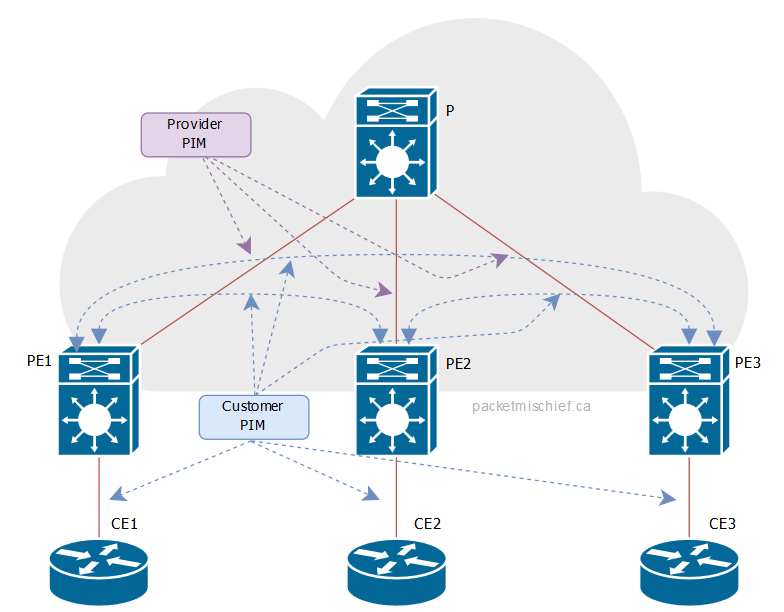
In each of the diagrams that follow, purple will represent the provider protocols/packets and cyan/blue will represent the customer protocols/packets.
The concept of a shared and source tree exist in a draft-rosen network, just like a non-MPLS network running PIM-SM.
The shared tree is called the Default Multicast Distribution Tree (MDT) and is built between all of the PEs in the multicast domain. The equivalent to the source tree is called the Data MDT which is built out only to those PE routers that have group members attached to them.
Each VPN in the network has its own Default and Data MDTs. And just like in regular old PIM-SM, traffic is first sent on the Default MDT and if traffic levels cross a configured threshold, a switchover is done to the Data MDT. Additionally, the Default MDT carries the VPN's multicast control traffic between PEs (PIM messages and such).
Each VPN is pre-configured with unique multicast addresses from the provider's multicast address space:
- A single multicast group to use for the Default MDT.
- A pool of multicast addresses to use for Data MDTs.
When a switchover is triggered from the Default to a Data MDT, the ingress PE grabs one of the addresses out of the pool and uses that group to transport the customer's traffic through the provider network. Just prior to switching over, the ingress PE sends a message on the Default MDT informing the other PEs that the customer's (S,G) is about to be sent to a new provider group. This gives the egress PEs that have attached recievers a chance to join this new group so they can continue to receive the stream. PEs that don't have attached receivers don't bother joining the group and no longer receive the traffic for that customer's (S,G).
While a Data MDT is active, there ends up being a dynamic one-to-one mapping between the customer's (S,G) traffic and the provider's group. Once the customer stops sending, the mapping will expire and the provider address is put back into the pool to be used again later.
In order to maintain segmentation of multicast VPN traffic, the actual data exchange between PE routers is done via GRE tunnels. This is true when a PE is sending multicast traffic that it received from an attached CE and also true when the PE is sending control traffic to other PEs.
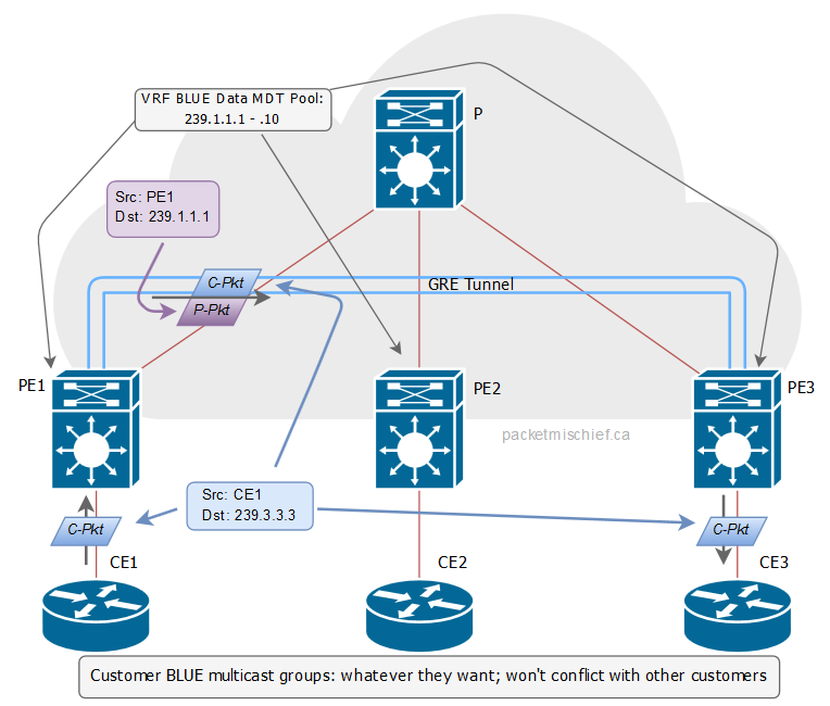
The GRE packets are delivered efficiently through the provider's network by using the provider's multicast groups: traffic on the Default MDT uses the default group and traffic on a Data MDT uses one of the groups from the Data MDT pool. Within the GRE packets is either the customer's multicast traffic (multicast-over-GRE-over-multicast) or PIM control traffic between PEs (PIM-multicast-over-GRE-over-multicast).
As shown in the digram, while CE1 is sending to 239.3.3.3, there is a dynamic mapping between (CE1, 239.3.3.3) and the provider's group 239.1.1.1, which was dynamically picked from the Data MDT pool for VRF BLUE. Once PE1 (the ingress PE) switches over to this Data MDT, it sends the GRE-encapsulated traffic to 239.1.1.1. The provider network — using regular PIM mechanics — delivers this traffic to PE3 since it's the only PE in the topology that has an attached receiver and has therefore joined 239.1.1.1.
If you've noticed by now that there is no actual use of MPLS or labels in draft-rosen, then you're absolutely correct! Draft-rosen uses native PIM in the provider network and GRE over the top for segmentation of customer traffic.
LSM⌗
LSM, as the name implies, uses labels to forward multicast traffic through the MPLS network.
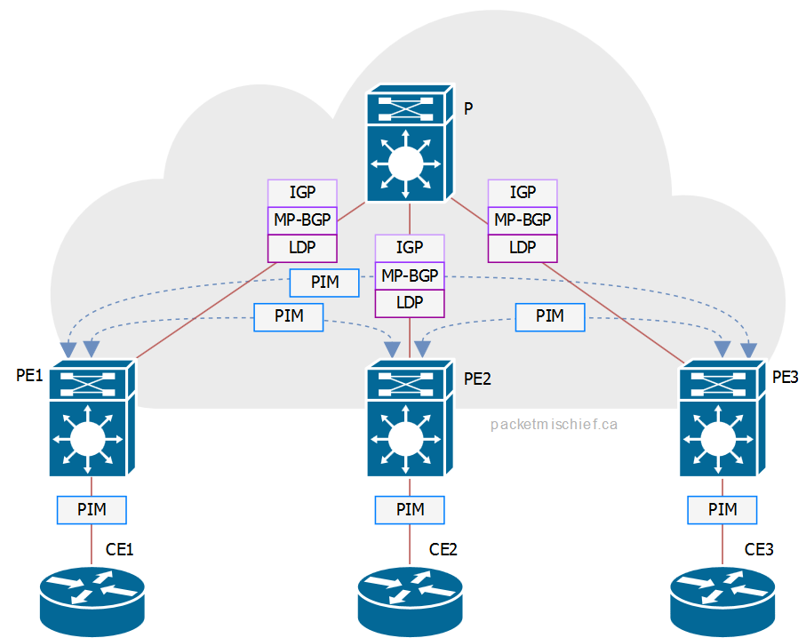
From a control plane perspective, the P routers don't run any additional protocols over and above regular unicast MPLS; they continue to run LDP and an IGP.
The PEs continue to run LDP, MP-BGP, an IGP, and unsurprisingly, they also run PIM. LSM takes advantage of extensions to LDP that enable signaling of multicast LSPs (so called "multicast LDP", or mLDP). Since the MPLS network will already be running LDP, LSM enables use of a single control plane protocol between the PE and P routers for both unicast and multicast traffic. Additionally, since LSM uses labels for packet forwarding, the data plane is also unified for unicast and multicast traffic.
Just like PIM-SM, LSM has a concept of a shared and source tree.
The shared tree is signaled as a multipoint-to-multipoint (MP2MP) LSP with the root of the tree being statically configured on a per-VPN basis. The root of the MP2MP tree can be a PE or a P router (any router that's speaking mLDP) and acts kind-sorta like a rendez-vous point in PIM-Bidir: the ingress PE will send traffic up the tree towards the root and the root then distributes traffic down the remaining branches of the tree.
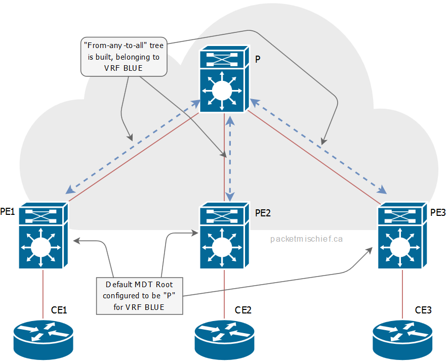
The default MDT is built as a MP2MP tree and is used for low-bandwidth application traffic and for control plane signalling between PEs. All PE and P routers will join the default MDT.
A source tree is signaled as a point-to-multipoint (P2MP) LSP with the root being the PE where the multicast traffic is entering the MPLS network. Similarly to PIM-SM, the P2MP tree is signaled backwards from the egress PE to the ingress PE with the egress PE determining the ingress PE's address by looking in the MP-BGP table for the next-hop towards the multicast source.
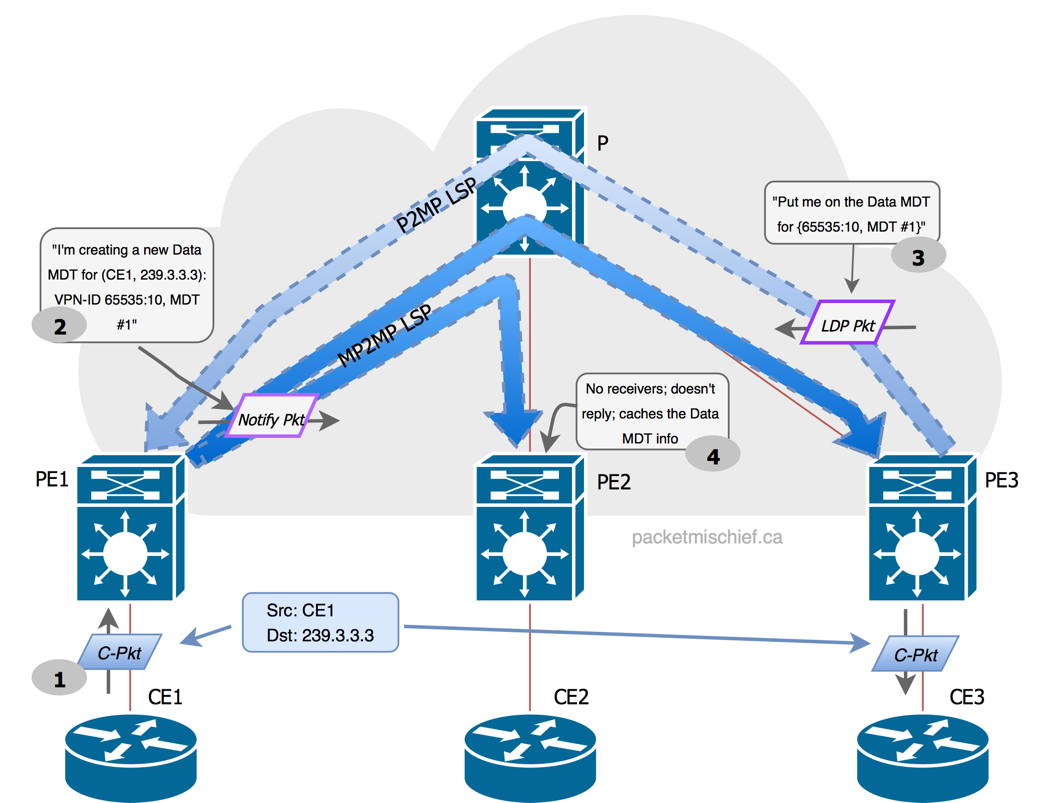
In order to uniquely identify a multicast LSP, the root address of the LSP is combined with an opaque value which is made up of the VPN ID and the Multicast Distribution Tree (MDT) number. When the traffic level for a specific multicast stream on the Default MDT crosses the configured switchover threshold, the ingress PE will signal that it is creating a Data MDT by multicasting a message on the Default MDT containing the (S,G) and {VPN-ID, MDT#} tuple of the new MDT. Any PE with receivers for that (S,G) will signal back to the ingress PE via LDP that it wishes to join this Data MDT by specifying the {VPN-ID, MDT#} tuple. In a later article, I'll show how that tuple can be used to look up the LSP's information.
The opaque value is used for signaling both P2MP and MP2MP trees.
- The default MDT is always MDT#0 - {VPN-ID, 0} tuple
- Dynamically signaled MDTs start at MDT#1 and increment upwards for each additional tree - {VPN-ID, N} tuple
The VPN-ID value is manually configured on the PE within the VRF. The format of the VPN-ID is OUI:ID and is commonly encoded as [ASN]:[per-VRF-number].
In order for the RPF check to succeed on the PEs, there is an LSP Virtual Interface (Lspvif) that's automatically created that points towards the MPLS cloud. This interface represents the head- and tail-end of the multicast LSPs and will show up in the incoming and outgoing interface list of an mroute.
Comparison and Summary⌗
| draft-rosen | LSM | |
| Provider control plane | PIM | LDP (with multicast extensions) |
| Provider data plane | GRE | MPLS label switching |
| PE-to-PE multicast signaling | PIM | PIM |
| P-router multicast state | 1 default group + N x data groups per VPN | No explicit multicast state, just labels |
| PE-router multicast state | 1 default group + N x data groups per VPN | No additional multicast state, just labels |
| Resiliency mechanisms | IGP convergence | MPLS fast re-route; IGP convergence |
LSM leverages the existing control and data plane mechanisms that are already in place for unicast MPLS traffic. This reduces control plane load, control plane state, and data plane state on the P-routers and serves to keep the P-routers very lean. From a scalability perspective, this is a good thing. LSM can also use the existing fast re-route capabilities of MPLS resulting in high resiliency and very fast convergence.
In the next article in this series, I will examine the configuration needed to make the LSM topology shown above fully functional.
References⌗
- RFC 6037: Cisco Systems' Solution for Multicast in BGP/MPLS IP VPNs (draft-rosen)
- RFC 6388: Label Distribution Protocol Extensions for Point-to-Multipoint and Multipoint-to-Multipoint Label Switched Paths
Disclaimer: The opinions and information expressed in this blog article are my own and not necessarily those of Cisco Systems.