Label Switched Multicast -- Packet Walk
This post is going to follow a multicast packet as it moves through a sample MPLS network using Label Switched Multicast (LSM). I'll show how the packet moves through the network by looking at the forwarding tables on different routers and also by doing some packet captures.
This post is part of a series I'm writing on LSM and if you're not already familiar with LSM, I recommend you go back and read the previous posts.
After reading this post you will be able to precisely describe how LSM forwarding works in the data plane and will be able to do some basic troubleshooting.
Let's get into the lab!
The Topology⌗
I'm using the same sample network as the previous posts with three CEs all in the same VRF, three PEs and just a single P router. Each of the CEs and PEs is multicast enabled.
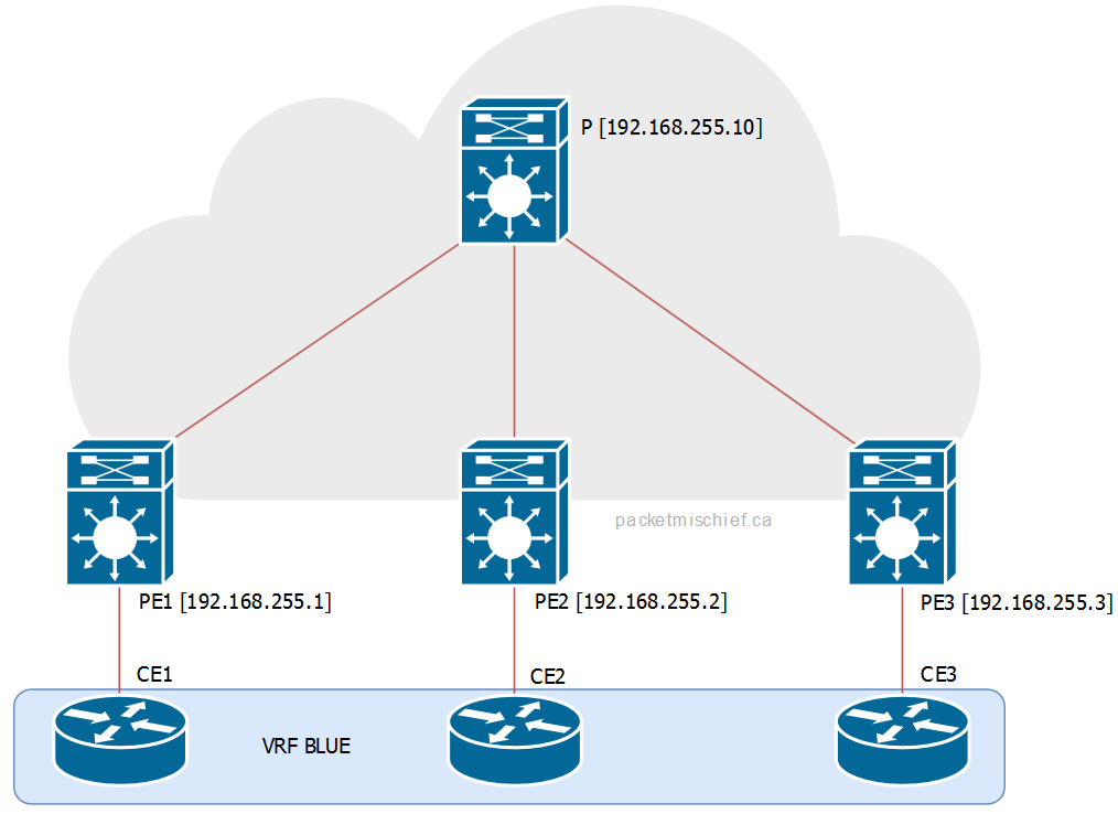
The scenario I'm going to be running here is CE1 sending an ICMP echo to the group 239.23.23.23. The receivers in this group are CE2 and CE3.
Between CE1 and PE1⌗
I'm going to just gloss over the traffic exchanged between CE1 and PE1 since nothing changes here when LSM is introduced. It's regular old IGMP (in this case, v2). CE1 is the source. PE1 is the PIM Designated Router. Life is grand.
MP2MP Tree on PE1⌗
In this scenario, PE1 is called the Ingress PE because it's the router that injects the multicast packet into the MPLS cloud. The Ingress PE chooses the LSP — either MP2MP or P2MP — to switch the packet down and from there the rest of the MPLS network does regular label switching.
The LSP for a (*,G) or (S,G) is stored as part of the MFIB entry, eg:
PE1#show ip mfib vrf BLUE 239.23.23.23
[..]
VRF BLUE
 (*,239.23.23.23) Flags: C
   SW Forwarding: 0/0/0/0, Other: 0/0/0
   Tunnel0 Flags: A
   Lspvif0, LSM/2 Flags: F NS
     Pkts: 0/0
Note a couple of things:
- This is a (*,G) entry since CE1 is not yet sending any traffic and therefore no one has signaled creation of the (S,G) tree yet
- There's only one outgoing interface and it's Lspvif0. This is the pseudo interface created by LSM which points towards the MPLS cloud.
- The LSM Multi-Destination Tree (MDT) index is 2
In my sample network PE1 is also the rendezvous point so it's going to always have a (*,G) for every group that has a receiver in the network. If PE1 was not the RP then (*,239.23.23.23) would not exist and the initial sequence of operations below would be different (there would be more steps). I can't really document every scenario so I just picked the one that is the most straight forward.
The LSM MDT index (2) is used to look at the mLDP database to see which LSP — and therefore which MDT — PE1 will put the traffic onto. The index is locally significant to the router and cannot be used to go hop by hop and examine every router using the same index number.
PE1#show mpls mldp database id 2
LSM ID : 1 (RNR LSM ID: 2)   Type: MP2MP   Uptime : 9w6d
  FEC Root           : 192.168.255.10
  Opaque decoded     : [mdt 65535:10 0]
  Opaque length      : 11 bytes
  Opaque value       : 02 000B 0655350000001000000000
  RNR active LSP     : (this entry)
  Upstream client(s) :
    192.168.255.10:0    [Active]
      Expires        : Never         Path Set ID  : 1
      Out Label (U)  : 19            Interface    : Ethernet0/1*
      Local Label (D): 26            Next Hop     : 10.1.1.10
  Replication client(s):
    MDT  (VRF BLUE)
      Uptime         : 9w6d          Path Set ID  : 2
      Interface      : Lspvif0
Items to take note of:
- This is a MP2MP tree (ie, a shared tree).
- The root of the tree is 192.168.255.10 (the P router). As mentioned in the previous post, the root of a MP2MP tree is manually configured on each PE.
- The opaque value for this MDT is {65535:10, 0}. This value will be used later to inspect the P and other PE routers.
- The outgoing label that PE1 will use for this LSP is 19.
Let's verify these findings with a packet capture between PE1 and P:

- In BLUE: CE1 (192.168.1.10) is sending to group 239.23.23.23 and PE1 is imposing a label of 19.
- In GREEN: CE2 and CE3 (192.168.2.10 and .3.10) are sending unicast replies and the MPLS network is using label 21 to deliver those packets to PE1.
MP2MP Tree on P⌗
There are a couple of different ways to inspect the forwarding tables on P.
The first way is to check the mLDP database just like on PE1. However since there is no MFIB entry on P there's no MDT index to look up. Instead, the opaque value is used as the lookup key:
P#show mpls mldp database opaque_type mdt 65535:10 0
LSM ID : 3   Type: MP2MP   Uptime : 10w0d
  FEC Root           : 192.168.255.10 (we are the root)
  Opaque decoded     : [mdt 65535:10 0]
  Opaque length      : 11 bytes
  Opaque value       : 02 000B 0655350000001000000000
  Upstream client(s) :
    None
      Expires        : N/A           Path Set ID  : 7
  Replication client(s):
    192.168.255.2:0
      Uptime         : 10w0d         Path Set ID  : 8
      Out label (D)  : 25            Interface    : Ethernet0/1*
      Local label (U): 20            Next Hop     : 10.1.2.2
    192.168.255.3:0
      Uptime         : 10w0d         Path Set ID  : A
      Out label (D)  : 24            Interface    : Ethernet0/2*
      Local label (U): 21            Next Hop     : 10.1.3.3
    192.168.255.1:0
      Uptime         : 9w6d          Path Set ID  : C
      Out label (D)  : 26            Interface    : Ethernet0/0*
      Local label (U): 19            Next Hop     : 10.1.1.1
Take note:
- As on PE1, this is a MP2MP tree.
- The opaque value is the same here as on PE1 (hence why it can be used as a key value when looking in the mLDP database on either router).
- P is connected to multiple branches of this MP2MP tree and has multiple replication clients; the list of clients is akin to the Outgoing Interface List in an mroute.
- The replication client list also contains the incoming (local) label. For example, the client 192.168.255.1 (PE1) has a local label of 19 which matches the label that PE1 used to send the packet to P.
The list of replication clients indicates that P will send this packet to two neighbors:
- 192.168.255.2 (which is PE2) using label 25 on interface eth0/1
- 192.168.255.3 (which is PE3) using label 24 on interface eth0/2
The other way to inspect the forward tables on P is to look directly into the MPLS LFIB using the incoming label of 19 as a key:
P#show mpls forwarding-table labels 19
Local      Outgoing   Prefix   Bytes Label   Outgoing   Next Hop
Label      Label      or       Switched      interface
                      Tun ID
19         25                  29883770      Et0/1      10.1.2.2
           24                  29883770      Et0/2      10.1.3.3
This output is a condensed version of what's in the mLDP database. It still shows what P will do though when it receives a packet with label 19 on it: it will replicate the packet out interfaces eth0/1 and eth0/2, popping label 19 off and pushing labels 25 and 24, respectively, on the replicated packets.
Confirming with a packet capture between P and PE3:

- In BLUE: CE1 (192.168.1.10) sending to the group in question and the packet has a label of 24.
- In GREEN: the unicast reply from CE3 (192.168.3.10) with the appropriate label stack (since this is a unicast reply, the labels in green are taken from the unicast FIB and aren't show in any of the outputs above so don't hunt for them).
MP2MP Tree on PE3⌗
In this scenario, PE3 is known as the Egress PE because it's taking an MPLS packet, popping all of the labels and routing a regular IP packet.
PE3's forwarding tables should be inspected from the context of IP multicast and not from LSM. This is because PE3 is only receiving a labeled packet, and is forwarding on an IP multicast packet.
To be thorough though, here's the LFIB entry for label 24:
PE3#show mpls forwarding-table labels 24
Local      Outgoing   Prefix   Bytes Label   Outgoing   Next Hop
Label      Label      or       Switched      interface
                      Tun ID
24    [T]  No Label   [V]      103866956     aggregate/BLUE
As this shows, PE3 will remove all labels ("No Label") and will do a regular IP route lookup in the VRF BLUE.
PE3#show ip mfib vrf BLUE 239.23.23.23
[...]
VRF BLUE
 (*,239.23.23.23) Flags: C
   SW Forwarding: 0/0/0/0, Other: 1/1/0
   Lspvif0, LSM/4 Flags: A NS
   Ethernet0/0.10 Flags: F NS
     Pkts: 0/0
The MFIB entry shows that the egress interface is eth0/0.10. From this point onward, regular Layer 2/Layer 3 multicast forwarding takes over.
P2MP Switchover⌗
All of the sections above are for the initial traffic that is sent across the shared/ MP2MP tree. The sections below are what happens during and after the switchover from MP2MP to P2MP.
In the sections below I'm going to use group 239.3.3.3 which has only CE3 as a receiver. This will demonstrate how the network will optimize the traffic flow so that PE2 no longer receives this traffic since it doesn't need it.
P2MP Switchover on PE3⌗
As mentioned in a previous article, the switchover to the P2MP tree is initiated by the Ingress PE. This is different than IP multicast where the router at the leaf of the tree initiates the formation of the source tree. In LSM, the Ingress PE tells the other PEs that it's about the create a new P2MP tree. The PEs that have receivers for that particular (S,G) will join this new P2MP tree and, after a slight delay to allow these joins to happen, the Ingress PE will start switching traffic down the P2MP LSP.
I find it's much easier to trace the flow of packets from the Ingress PE so that's where I like to start.
When traffic levels on the MP2MP tree cross a preconfigured threshold (which by default is 0 kbps, or "after the first packet is received"), the Ingress PE sends the signal that it's about to create a new P2MP LSP.
With CE1 sending continuous traffic to 239.3.3.3, PE1 happily sends the first few packets on the MP2MP LSP which PE3 receives on label 24:
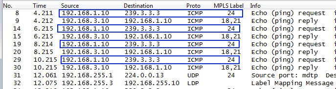
At a certain point PE1 sends a UDP message (packet #31) on the MP2MP tree to all PIM routers (224.0.0.13) announcing that it is about to create a new P2MP tree. Unfortunately Wireshark doesn't have a decoder for the payload of this UDP packet so I can't show a screenshot, but the packet contains the (S,G) information along with the opaque value that PE1 has created for the new P2MP tree.
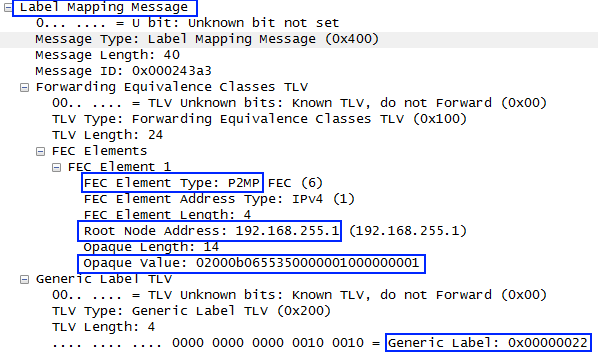
Right after that (packet #32), PE3 sends an LDP mapping message upstream that contains:
- The FEC type of "P2MP"
- The root node's address "192.168.255.1" (which is the Ingress PE)
- The encoded opaque value for the new P2MP tree
- The label that it has allocated for its leg of the P2MP tree (0x22, 34 decimal)
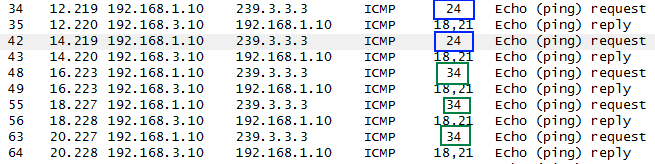
While the LDP mapping messages are moving throughout the network, PE1 continues to send the multicast traffic on the MP2MP tree until eventually switching over to the newly formed P2MP tree. This is seen as a change of the incoming label on PE3 from 24 (MP2MP) to 34 (P2MP):
P2MP Tree on PE1⌗
Examination of PE1 is really the same as when looking at the MP2MP tree. Start by looking in the MFIB of VRF BLUE:
PE1#show ip mfib vrf BLUE 239.3.3.3 192.168.1.10
VRF BLUE
 (192.168.1.10,239.3.3.3) Flags: ET
   SW Forwarding: 6/0/100/0, Other: 0/0/0
   Ethernet0/0.10 Flags: A
   Lspvif0, LSM/2D Flags: F NS
     Pkts: 2/0
- Since the intent is to examine the P2MP tree, which is akin to the source tree, the source IP address is given in the command.
- The LSM MDT index is 0x2D.
- The flags on this (S,G) entry are "ET", or Exceeded Threshold, meaning that this entry was created in response to the data rate exceeding the configured threshold.
As before, the LSM MDT index is used to inspect the mLDP database:
PE1#show mpls mldp database id 2d
LSM ID : 2D   Type: P2MP   Uptime : 00:00:26
  FEC Root           : 192.168.255.1 (we are the root)
  Opaque decoded     : [mdt 65535:10 1]
  Opaque length      : 11 bytes
  Opaque value       : 02 000B 0655350000001000000001
  Upstream client(s) :
    None
      Expires        : N/A           Path Set ID  : 2D
  Replication client(s):
    MDT  (VRF BLUE)
      Uptime         : 00:00:26      Path Set ID  : None
      Interface      : Lspvif0
    192.168.255.10:0
      Uptime         : 00:00:26      Path Set ID  : None
      Out label (D)  : 27            Interface    : Ethernet0/1*
      Local label (U): None          Next Hop     : 10.1.1.10
- LSP type is P2MP
- The opaque value is {65535:10, 1}
- The outgoing MPLS label is 27 towards P
There isn't much difference on PE1 (as the Ingress PE) between the MP2MP tree and P2MP tree. All PE1 is really doing is choosing a different LSP towards router P.
P2MP Tree on P⌗
Since router P sits on multiple branches of the MP2MP tree, this is where some differences are found.
P#show mpls mldp database opaque_type mdt 65535:10 1
LSM ID : 2C   Type: P2MP   Uptime : 00:03:27
  FEC Root           : 192.168.255.1
  Opaque decoded     : [mdt 65535:10 1]
  Opaque length      : 11 bytes
  Opaque value       : 02 000B 0655350000001000000001
  Upstream client(s) :
    192.168.255.1:0    [Active]
      Expires        : Never         Path Set ID  : 36
      Out Label (U)  : None          Interface    : Ethernet0/0*
      Local Label (D): 27            Next Hop     : 10.1.1.1
  Replication client(s):
    192.168.255.3:0
      Uptime         : 00:03:27      Path Set ID  : None
      Out label (D)  : 34            Interface    : Ethernet0/2*
      Local label (U): None          Next Hop     : 10.1.3.3
- Router P has also switched to the P2MP tree that PE1 created.
- There is only a single replication client, PE3, on interface eth0/2.
Unlike the MP2MP tree which goes to every PE, this new P2MP tree only reaches the PEs that have receivers interested in receiving the (S,G) traffic. Since PE2 does not have any interested receivers, it does not join the P2MP tree.
Summary⌗
There's an awful lot of detail and bits and bytes in this post but the most important takeaway is knowing that in order to trace LSM traffic within the MPLS cloud, it's necessary to find the right MDT and trace the MDT. Outside of the cloud it's possible to trace the (*,G) or (S,G) trees, however there are no (*,G) or (S,G) constructs within the MPLS cloud: it's all label based.
By starting at the Ingress PE, it's straightforward to map an (S,G) to an MDT and then begin tracing the MDT through the cloud to its various destinations. The MDT can be traced hop by hop by using labels (just like tracing unicast traffic) or by using the opaque value to look in the mLDP database.
In the next post, I'll cover some Frequently Asked Questions about LSM that will add some more detail in certain areas and can be used as a quick reference guide.
Disclaimer: The opinions and information expressed in this blog article are my own and not necessarily those of Cisco Systems.