VRFs and Shared Services Cheating with Junos
The shared services area of the network is meant to provide common services — such as DNS, DHCP, and Internet access — to multiple logical networks/VRFs/customers. Cisco publishes a validated design for shared services that describes the use of multiple virtual firewalls and routers to provide connectivity between the shared services module and the VRFs in the network. I'm going to describe a method of collapsing the shared services firewalls and virtual routers into a single instance running on a single box using some of the features found in Juniper's Junos platform.
This is the third post in my series on virtual routing. Other articles in the series are
Shared Services Objectives⌗
The shared services module has 3 main objectives:
- Provide shared network services to multiple VRFs by way of common infrastructure
- Permit select traffic exchange between VRFs and shared services resources
- Prevent traffic exchange between VRFs
The last one isn't a reason for setting up a shared services module (ie, you don't setup shared services in order to try and keep traffic from passing between VRFs) but instead is a very important design objective. Since the shared services module has connections into multiple VRFs and is exchanging routes with them, due care is needed to prevent the shared services area from becoming a transit path between VRFs.
Now, you might think that since you're connecting your VRFs together via a common area that you're increasing your risk of traffic crossing between VRFs (ie, guests being able to access your corporate network resources). The natural reaction is to stuff some firewalls in the mix. Filter everything in and out of the VRFs! Firewalls will keep us safe! Keep in mind though that each VRF only forwards traffic toward a destination if it has a route for that destination. As long as routes are being filtered properly in the shared services area, VRF A will not contain routes for networks in VRF B (and vice-versa). If a user sends a packet into VRF A with a destination address belonging to a network in VRF B, the worst case is that the packet will follow the default route in VRF A (which probably leads towards the Internet exit point in that VRF) and best case it will just be dropped because there is no matching route. Either way, even without a firewall, traffic does not cross from A to B.
Remember: Traffic will not be directed towards (or through) the shared services area unless there is a matching route present in a VRF's routing table that points towards the shared services area.
Having said that, we can't throw the firewall out the window. Objective #2 is to provide selective traffic exchange between VRFs and the shared services and that's where the firewalls come in. They will be used to permit only the traffic that corresponds to the specific services that are being provided. For example, if one of the shared services is DNS, only allowing port 53 traffic into the shared services area.
Cheating⌗
The basic topology for this shared services module is shown here:
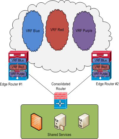
The consolidated router in this topology is actually a Juniper SRX firewall running Junos and will be performing route exchange, route filtering, and firewall duties all in the same physical box and in a single firewall instance.
The consolidated router is configured with one routing instance for each VRF in the network. Each instance is of type "virtual-router" and is used to exchange routes with the VRFs in the network as well as containerize those routes.
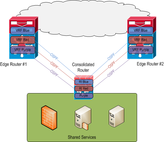
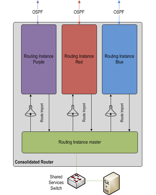
By importing explicit prefixes between each routing instance and the global, aka "master" routing instance, route filtering is achieved. The OSPF process running within each routing instance is then directed to pick up these imported prefixes and advertise them to its neighbors (which are OSPF processes running in the VRFs on the edge routers).
OSPF has no ability to filter outgoing route updates. The edge routers could be configured with distribute lists to prevent incoming route updates from entering their routing tables however this would not prevent the prefixes from being present in the OSPF link state database. More importantly, this method creates two points of management for route filtering vs. a single point on the consolidated router.
BGP may be a better protocol to use between the consolidated router and the edge routers as it would more easily allow filtering of sent and received prefixes. It would probably remove the need for routing instances at all (thus making the design more in line with Cisco's validated design of having a single routing table in the shared services area). However I'm basing this post on a real life deployment which actually used OSPF.
By employing routing instances on the consolidated router it's possible to:
- Accurately filter routes in and out of the shared services area
- Extend and reuse the concepts of virtualized routing tables which are already being used in the core of the network (and therefore something we're already familiar with)
- Avoid the need to manage route filtering in more than one location; everything is done on the consolidated router
On top of this, a firewall policy will be deployed that permits only specific traffic based on typical 5-tuple information. So even though a VRF has full routes for the shared services area, the firewall policy will control exactly what traffic is allowed into (and out of) the area.
The Configuration⌗
For brevity, I'm only going to show the configuration related to the blue VRF/routing instance. I'm also not going to show the firewall security policy as this post is meant to focus on the routing configuration.
First, configure the instance.
routing-instances {
    blue {
        instance-type virtual-router;
        interface ge-2/0/1.0;
        interface ge-3/0/1.0;
        protocols {
            ospf {
                area 0.0.0.0 {
                    interface ge-2/0/1.0;
                    interface ge-3/0/1.0;
                }
            }
        }
    }
}
This gives us a basic virtual-router instance with two interfaces bound to it and OSPF running within it. The edge routers should be configured similarly with with their respective interfaces bound to the blue VRF and OSPF enabled.
The two interfaces ge-2/0/1.0 and ge-3/0/1.0 face the edge routers and are configured as regular point-to-point /30 interfaces.
interfaces {
    ge-2/0/1 {
        description "Connects to Edge Router #1";
        unit 0 {
            family inet {
                address 10.2.0.1/30;
            }
        }
    }
}
At this point the blue routing instance should contain all of the routes from the blue VRF.
The interface facing the shared services area is a regular interface with no associated routing instance; it's part of the default instance (named "master" on the SRX platform).
interfaces {
    ge-2/0/0 {
        description "Connects to shared services switch";
        unit 0 {
            family inet {
                address 10.10.0.1/24;
            }
        }
    }
}
At this point the "master" routing instance only contains the "direct" route for the /24 network configured on ge-2/0/0.0.
Now, to import routes into "master" from "blue", configure an appropriate policy statement that selects routes in "blue" and apply that statement as an import policy on the "master" routing instance.
policy-options {
    policy-statement routes_from_vrfs_to_master {
        term from_blue {
            from {
                instance blue;
            }
            then accept;
        }
        term default_deny {
            then reject;
        }
    }
}
routing-options {
     instance-import routes_from_vrfs_to_master;
}
This config will suck all the routes from the "blue" routing instance into the "master" instance. To be a little more granular, a prefix-list could be used in the "from" stanza of the policy-statement to only permit specific prefixes but that would limit reachability to only a portion of the blue network. The default_deny term is important; you'll want to make sure that's the last term in the policy-statement.
Now to do the reverse and import routes into blue from master. This is where the filtering becomes relevant.
policy-options {
    prefix-list ss_prefixes {
        10.10.0.1/24;
    }
}
This prefix-list specifies the network(s) that belong to the shared services area and is used to filter the list of routes imported into blue.
policy-options {
    policy-statement routes_from_ss_to_vrfs {
        term 1 {
            from {
                instance master;
                prefix-list ss_prefixes;
            }
            then accept;
        }
        term default_deny {
            then reject;
        }
    }
}
The above chunk selects prefixes in the master table that match the prefix-list.
routing-instances {
    blue {
        routing-options {
            instance-import routes_from_ss_to_vrfs;
         }
        protocols {
            ospf {
                export routes_from_ss_to_vrfs;
            }
        }
    }
}
And this chunk applies the policy in order to:
- Import the routes into blue from master
- Export the routes out of blue to OSPF so that the prefixes are advertised to the edge routers
At this point traffic should flow bidirectionally between shared services and the "blue" VRF while at the same time preventing traffic flow between "blue" and any other VRF.