Getting Traffic to a Virtual Firepower Sensor
I wanted to jot down some quick notes relating to running a virtual Firepower sensor on ESXi and how to validate that all the settings are correct for getting traffic from the physical network down into the sensor.
Firepower is the name of Cisco's (formerly Sourcefire's) so-called Next-Gen IPS. The IPS comes in many form-factors, including beefy physical appliances, integrated into the ASA firewall, and as a discrete virtual machine.
Since the virtual machine (likely) does not sit in-line of the traffic that needs to be monitored, traffic needs to be fed into the VM via some method such as a SPAN port or a tap of some sort.
1 - Validate vSwitch Settings⌗
This is probably not a very real-world example since most environments will be running some form of distributed vSwitch (dvSwitch) and not the regular vSwitch, but all I've got in my lab is the vSwitch, so work with me. The same considerations apply when running a dvSwitch.
Ensure that the port-group where you're attaching the NGIPSv allows promiscuous mode. The NGIPSv acts as sniffer and will attempt to put its NICs into promisc mode.

Set this either at the vSwitch level or at the port group level.
2 - SPAN Traffic to the Sensor⌗
As mentioned above, traffic needs to be copied to the sensor so it has something to look at. Since a virtual sensor almost certainly isn't in the direct traffic path, a SPAN port from the network makes the most sense... except there's no physical port on the sensor to SPAN to!
Cisco IOS allows SPANing traffic to a VLAN: it's basically like making a copy of the packet from the VLAN being monitoring onto a second VLAN which is plumbed into the sensor. In my lab, I'm monitoring VLAN 100 and SPANing onto 2100.
Make sure the SPAN VLAN is configured with the remote-span keyword to designate this VLAN as such.
vlan 2100
 name Sniff_Servers
 remote-span
Now configure the SPAN session:
monitor session <id> source vlan 100 rx
monitor session <id> destination remote vlan 2100
- The
idis an arbitrary number which identifies the SPAN session on the switch. - Note the use of the
rxkeyword on the "source" line: when SPANing a VLAN, it's almost always desirable to SPAN eitherrxortx, but notboth. When usingboth, two copies of each packet will be sent: one when the switch receives the packet on the ingress interface and one when the switch transmits the packet on the egress interface.
Lastly, make sure the SPAN destination VLAN is added to the trunk port(s) facing the ESXi host.
3 - Validate Traffic is Being Received⌗
With the network portion configured, validate that the sensor is receiving traffic by logging in with the admin account and using the show traffic-statistics command. Look for incrementing Rx Bytes.
> show traffic-statistics
-----------------[ Traffic Status ]-----------------
Name                      : eth1
Transmitted Bytes (TX)    : 0
Received Bytes (RX)       : 31858466910
Dropped Packets           : 0
Speed                     : 1000
Port                      : Ethernet
Duplex                    : Full
Link                      : Up
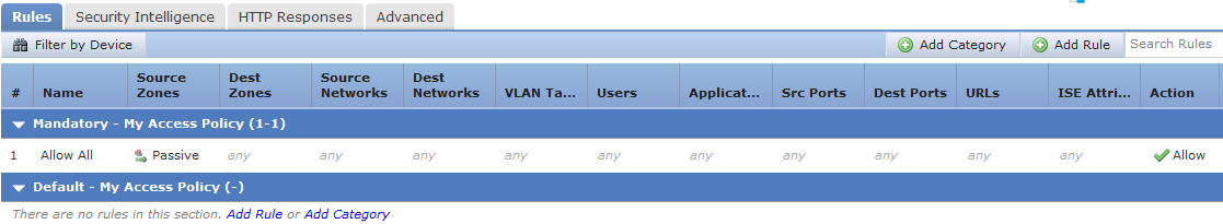
4 - Add an Access Policy⌗
Now in Firepower Management Center (FMC), the graphs should begin to populate and events should begin to show up. If not, ensure you have at least one Access Policy and that the policy contains at least one rule! If there are no Access Policy rules created, no traffic or events will be registered in FMC. Create a rule and make sure it's deployed to the NGIPSv.
This is true even though the IPS is in "passive" mode and not actively blocking traffic.
5 - I'm Not Seeing All of My Traffic!⌗
Once everything is populating into FMC correctly and the NGIPSv is reporting data, there may be some traffic flows that are not being recorded.
- Remember: the SPAN session is coming from the physical network. If there are flows that never leave the virtual network, the physical network will not see them and they will not be captured by the SPAN. In order to get this traffic, the vSwitch being used must support a similar feature to SPAN in Cisco IOS.
- Consider the path of traffic through the network and whether the traffic for the missing flows traverses the switch where the SPAN is set up. In most cases it makes sense to create the SPAN on an aggregation switch since that's a nice concentration point in the network, but that doesn't automatically mean every single flow will be seen by that switch. It may be necessary to move the SPAN to another switch or to setup multiple SPANs.
Disclaimer: The opinions and information expressed in this blog article are my own and not necessarily those of Cisco Systems.