OSPF vs EIGRP for DMVPN
In this post I'm going to look at the characteristics of OSPF and EIGRP when used in a Dynamic Multipoint VPN (DMVPN). I will do my best not to play favorites and instead stick to the facts (yes, I do have a preference :-). To that end I will back everything up with data from my lab. The focus areas of the comparison will be:
- Scalability of the hub router's control plane
- Overall control plane stability
- Traffic engineering
This post won't go into any background on how DMVPN works. If you're not yet familiar with DMVPN, I recommend watching these introductory videos by Brian McGahan. This post also does not do a deep dive on OSPF or EIGRP. I'm making the assumption that you're already familiar with the different LSA types in OSPF and general functions of EIGRP.
After reading this post you should be able to describe the pros and cons of OSPF and EIGRP in the three areas listed above and incorporate this knowlege into a DMVPN design.
Contents⌗
- Lab Topology
- OSPF Design Choice: Where Does Area 0 Go?
- Filtering Routing Updates
- Periodic Routing Updates
- Traffic Engineering
- OSPF Tuning
- EIGRP Tuning
- Summary
Introduction⌗
OSPF and EIGRP perform the same function — advertising network reachability information — but they perform this function in very different ways.
OSPF is a link state protocol which means it creates a "link state database" which is replicated to each OSPF speaker within an OSPF area. OSPF update messages — called Link State Updates (LSUs) — are actually how this database is synchronized from one speaker to another. OSPF does not directly exchange routes between intra-area neighbors! Think of these messages instead as database replication messages. The routing table entries are generated by running the Shortest Path First (SPF) algorithm against the local copy of the database. I'm calling out this intra-area behavior specifically because it will be relevant further on.
The important part to remember here is: all routers in an OSPF area must have the same copy of the database. Put another way: an OSPF update advertised into an area must be seen and processed by every router in that area in order to ensure that all routers in the area have a synchronized copy of the database.
EIGRP is based on distance vector routing principles which means it doesn't exchange database updates but instead exchanges routing information directly. An EIGRP speaker puts these routing updates into a data structure called the EIGRP topology table and then runs the Diffusing Update Algorithm (DUAL) over the table in order to generate the routing table entries. The topology table is its own unique entity on each EIGRP speaker and does not need to be synchronized amongst them in any way.
These characteristics of the protocols are very important to understand when reviewing the details below because they form the basis for why each protocol scales the way it does.
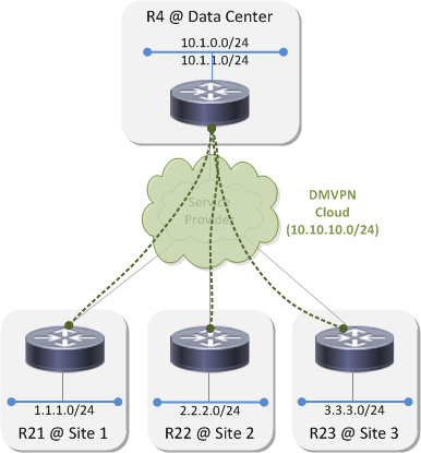
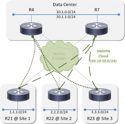
Lab Topology⌗
This is the example network I'll be using throughout this post:
OSPF Design Choice: Where Does Area 0 Go?⌗
When using OSPF on a DMVPN a choice has to be made about where to place area 0. There are three options:
- Area 0 behind the hub; a non-zero area across the DMVPN and at the sites
- Area 0 on the DMVPN; a unique non-zero area at each spoke site
- Area 0 everywhere
I'm going to discount the third option right off the bat because it has the worst scaling properties and the highest change of control plane instability. It's not recommended.
Topology 1⌗
Topology 1 looks like this:
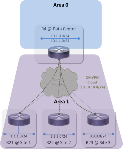
Because OSPF uses a two-level hierarchy where area 0 is the backbone and all non-zero areas are attached to the backbone, placing area 0 behind the hub means that everything below the hub in the diagram must belong to the same non-zero area. What's that you say? Virtual-links? I'll pretend I didn't hear that :-) With this design the DMVPN cloud itself as well as every spoke site LAN are part of the same area.
The natural question is: why can't each spoke be part of its own area? And the answer is: because the hub uses a single, multipoint tunnel interface to connect to every site in the DMVPN cloud and an interface cannot belong to more than one OSPF area. In order for the spoke sites to be part of the same DMVPN, they must terminate on the same tunnel interface on the hub which means they must be part of the same OSPF area.
R4#show ip ospf neighbor

Neighbor ID     Pri   State        Dead Time   Address         Interface
10.1.21.21        0   FULL/  -     00:00:38    10.10.10.21     Tunnel0
10.1.23.23        0   FULL/  -     00:00:31    10.10.10.23     Tunnel0
10.1.22.22        0   FULL/  -     00:00:32    10.10.10.22     Tunnel0
In this topology, R4, R21, R22 and R23 all have the same OSPF database in area 1 and R4 is the Area Border Router (ABR) between area 1 and the backbone. When any one of those routers sends an LSU into area 1, all of the other routers process that LSU and update their database and then also perform an SPF run.
Topology 2⌗
Topology 2 looks like this:
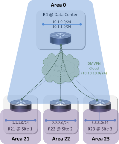
In this topology area 0 is extended across the DMVPN to the spoke routers. The spoke routers are the ABRs this time and each connect their own unique area to the backbone. The databases on R4, R21, R22 and R23 are still all the same but this time it's for area 0. And, since area 0 extends up above R4 and into the data center, all of the OSPF speakers in the datacenter also share the same area 0 database with R4, R21, R22 and R23. Any LSU sent into area 0 now has to be processed by those four routers as well as all of the OSPF devices attached to area 0 in the datacenter.
Filtering Routing Updates⌗
One way to design stability into a network is to limit the scope of control plane messages such as routing updates. When a router receives a routing update, it's a signal that it must rebuild its protocol-specific tables, send its own copy of the update out to its neighbors, rebuild the routing table and then program the forwarding table. It's a lot of work and does place some burden on the device so it's best to scope routing updates so that only the devices that really need to know about the update perform the reconvergence steps and the rest just continue on, blissfully unaware.
Below is a description of the capabilities that OSPF and EIGRP have for scoping routing updates.
Filtering in OSPF Topology 1⌗
OSPF has a hard rule that update messages cannot be filtered within an area. This ties back to the rule above that all routers within an area must have the same copy of the database. In order for this to happen, all routers must receive all updates. So no filtering.
Yes, you can apply a distribute-list inbound under the OSPF process however that only filters OSPF routes from entering the routing table. It does not filter OSPF Link State Update messages. Even if a distribute-list is applied, OSPF still processes LSUs, updates the database and runs SPF.
The practical impact of this is that if there is a topology change at Site 1 — eg, an interface goes down on an OSPF speaker, be it R21 or some other router at the site — that triggers an update to that device's OSPF database and the generation of at least one LSU to announce that change to the rest of the network.
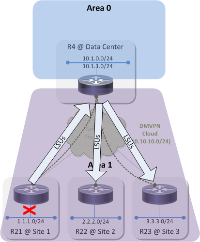
That small topology change in Site 1 causes LSUs to propagate throughout the area and causes each OSPF speaker to update its database and run SPF. This small change in Site 1 causes control plane churn in all of the other sites. This is no big deal in a network that resembles the sample topology but imagine a network with hundreds or even thousands of spoke sites. Now it's a big deal because there's hundreds/thousands of networks where links can be going up and down, all causing LSUs to be flooded across the whole DMVPN which in turn causes every OSPF speaker in every site to reconverge.
There is no way to scope routing updates within an OSPF area and therefore no way to prevent control plane churn within the area when a link in a site flaps.
Example: When manually dropping the link to the 1.1.1.0/24 network on R21:
R21(config-if)#do show clock
*20:27:03.750 MST Mon Jun 15 2015
R21(config-if)#shut
Router R22 receives an LSU from R21 and performs a full SPF run:
R22#show ip ospf events

            OSPF Router with ID (10.1.22.22) (Process ID 1)

1    *Jun 15 20:27:16.566: Timer Exp:  if_ack_delayed  0x3A02E98
2    *Jun 15 20:27:14.065: Rcv Changed Type-1 LSA, LSID 10.1.21.21, Adv-Rtr 10.1.21.21, Seq# 80000003, Age 2, Area 1
3    *Jun 15 20:27:14.065: Schedule SPF, Topo Base, Area 1, spf-type Full, Change in LSA Type RLSID 10.1.21.21, Adv-Rtr 10.1.21.21
The one place routing updates can be scoped is between area 1 and area 0. R4 can be configured to advertise a summary route(s) into area 0 that represents the subnets at the DMVPN sites. The act of having a summary route in place prevents the advertisement of specific subnet routes which means there are no routing updates sent into area 0 when a link flaps in a DMVPN site. The practical impact of this is that none of the OSPF speakers in area 0 — or any other areas attached to area 0 — experience any control plane churn.
Filtering in OSPF Topology 2⌗
Topology 2 has the same constraints but things have just moved around a bit. R21, R22 and R23 are now the ABRs and they can advertise summary routes that represent their respective sites into area 0. This isolates area 0 from any topology changes within the sites. The challenge now is that any instability on the DMVPN cloud itself will be felt by OSPF speakers up in the datacenter. For example, if R21 has an unreliable connection to the service provider which causes its DMVPN interface to flap, that will trigger LSU flooding on R4 which will be flooded up into the datacenter to the rest of area 0.
Example: The WAN interface on R21 goes down:
R21(config-if)#do show clock
*20:43:53.807 MST Mon Jun 15 2015
R21(config-if)#shut
After the OSPF dead timer reaches zero on R4, the adjacency is brought down and R4 floods LSUs into area 0. These LSUs reach R22 and R23 and also R5 in the data center:
R22#show ip ospf events

 OSPF Router with ID (10.1.22.22) (Process ID 1)

[..]
32 *Jun 15 20:44:35.613: RIB Delete, Topo Base, dest 10.10.10.21, mask 255.255.255.255, gw 10.10.10.4, via Tunnel0, source 10.1.21.21, type Intra
[..]
34 *Jun 15 20:44:35.613: Schedule SPF, Topo Base, Area 0, spf-type Prefix Recalculation, Change in LSA Type SN
[..]
38 *Jun 15 20:44:35.614: Starting Intra-Area SPF, Topo Base, Area 0, spf_type Full
39 *Jun 15 20:44:35.614: Starting SPF, Topo Base, wait-interval 5000ms
R5#show ip ospf events

            OSPF Router with ID (10.1.5.5) (Process ID 1)

22   *Jun 15 20:44:35.601: RIB Delete, Topo Base, dest 10.10.10.21, mask 255.255.255.255, gw 10.2.45.4, via Ethernet0/0, source 10.1.21.21, type Intra
[..]
24   *Jun 15 20:44:35.601: Schedule SPF, Topo Base, Area 0, spf-type Prefix Recalculation, Change in LSA Type SN
[..]
29   *Jun 15 20:44:35.601: Starting Intra-Area SPF, Topo Base, Area 0, spf_type Full
30   *Jun 15 20:44:35.601: Starting SPF, Topo Base, wait-interval 5000ms
Again, this might not be a big deal in a small network, but with hundreds or thousands of spokes, the risk is high. The stability of the control plane in the datacenter is now tied to the overall stability of the underlying service provider. And once again, because they're in the same area, there is no way to insulate the datacenter from topology changes on the DMVPN cloud.
Filtering with EIGRP⌗
EIGRP routing updates will be advertised throughout the entire EIGRP AS, very similarly to how OSPF advertises updates throughout an area. Without scoping the updates, every EIGRP speaker in the AS will reconverge when a link flaps in a site.
By default, EIGRP follows the split-horizon rule so in this topology, updates from R21 would actually not be received by R22 or R23 because they come in and would go out the same tunnel interface on R4. I'm overlooking that here and assuming the worst-case scenario that split-horizon has been disabled on R4's multipoint tunnel interface.
EIGRP allows any router, anywhere in the network to create a summary route and just like with OSPF, a summary route will block advertisement of the component subnets. Summary routes can be created at both levels of the network:
- At routers R21, R22 and R23 to summarize their respective sites into the DMVPN cloud
- At R4 to summarize the DMVPN cloud and possibly even summarize the summaries from the spoke routers into the datacenter
With this configuration, there's a high degree of isolation between all points of the network which will prevent control plane churn when a link flaps anywhere in the network.
Example without summarization: the interface to the 1.1.1.0/24 network on R21 goes down:
R21(config-if)#do show clock
*20:58:20.703 MST Mon Jun 15 2015
R21(config-if)#shut
This causes a routing update to hit every EIGRP router in the AS:
R22#show ip eigrp events
Event information for AS 123:
1    20:58:21.764 NDB delete: 1.1.1.0/24 1
2    20:58:21.764 RDB delete: 1.1.1.0/24 10.10.10.4
[..]

R4#show ip eigrp events
Event information for AS 123:
1    20:58:21.823 NDB delete: 1.1.1.0/24 1
2    20:58:21.823 RDB delete: 1.1.1.0/24 10.10.10.21
[..]
When a summary route is configured on R21's tunnel interface and the interface to 1.1.1.0/24 goes down, R21 no longer propogates a routing update.
interface Tunnel0
 ! Configure a summary route of 1.1.0.0/16
 ip summary-address eigrp 123 1.1.0.0 255.255.0.0
Filtering Routing Updates: Summary⌗
| OSPF | EIGRP |
| Every routing update within an area is processed by every device in that area | Every routing update within an area is processed by every device in that area |
| Routing updates within an area cannot be filtered | Routing updates within an EIGRP AS can be filtered at any point via summarization |
| Topology changes always cause a routing reconvergence on every router in the area | The impact of topology changes can be scoped by using summarization and route filtering |
| OSPF routing updates can only be scoped at area boundaries; there can only be 1 area boundary anywhere near the DMVPN | EIGRP routing updates can be scoped at any place in the network and even at multiple places simultaneously |
Periodic Routing Updates⌗
One further thing to note about OSPF with respect to routing updates is that it refreshes every Link State Advertisement (LSA) at 30 minute intervals from the time the LSA was first advertised. So even in a very stable network with few link flaps, there is still overhead on the control plane caused by these regularly occurring updates.
The 30 minute refresh time is a constant and cannot be adjusted.
EIGRP does not send periodic routing updates.
Traffic Engineering⌗
I'm going to change the topology a little bit for this section by adding a second hub router at the data center. Each spoke router now has two viable paths to reach the two subnets in the datacenter. The sections below will look at how traffic engineering can be performed with OSPF and then with EIGRP.
TE with OSPF⌗
The allocation of OSPF areas isn't relevant for this topic which is why the diagram doesn't show them.
OSPF assigns a metric to a route by adding up the costs of all the links along the path between the local router and the destination. A cost is assigned to a link; costs are not assigned to routes themselves. For example, if R4 advertises the prefixes 10.1.0.0/24 and 10.1.1.0/24 to R21 and R21 receives both OSPF updates on its tunnel interface, then OSPF on R21 will add the same cost value to the metric of both routes. OSPF will not — and cannot — add 100 to the metric of 10.1.0.0/24 and 200 to the metric of 10.1.1.0/24 (for example).
R21#show ip ospf interface tunnel0 | begin Cost
  Process ID 1, Router ID 10.1.21.21, Network Type POINT_TO_MULTIPOINT, Cost: 1000
As another example, let's say R21 receives an update for the 10.1.0.0/24 network from both R4 and R7. Since these updates come into R21 on the same tunnel interface (because all three routers are part of the same DMVPN cloud), OSPF on R21 will still add the same cost value to the metric of both routes. Even in this case, OSPF will not — and cannot — add a smaller cost to the route received from one hub and a larger cost to the route received from the other hub.
There are two traffic engineering scenarios I'm going to explore:
- Active/standby hubs - where spoke routers send all of their traffic to R4 and only route to R7 if R4 goes away
- Per-prefix active/standby hubs - where spoke routers send traffic for certain prefixes to R4 and use R7 as a backup and where they send other prefixes to R7 and use R4 as a backup
OSPF with Active/Standby Hubs⌗
As I established above, OSPF on the spoke routers cannot increment the metric of a route by a little bit when it's received from R4 and by a lot when it's received from R7. Because of this the traffic engineering cannot be configured on the spokes.
What can be done instead is to modify R7's OSPF interface cost towards the two data center subnets so that it's advertising a higher metric out to the spokes.
Before adjusting R7's metric, R21 has two equal cost routes via R4 and R7:
R21#show ip route 10.1.0.0
Routing entry for 10.1.0.0/24
  Known via "ospf 1", distance 110, metric 1021, type inter area
  Last update from 10.10.10.7 on Tunnel0, 00:04:41 ago
  Routing Descriptor Blocks:
    10.10.10.7, from 10.1.7.7, 00:04:41 ago, via Tunnel0
      Route metric is 1021, traffic share count is 1
  * 10.10.10.4, from 10.1.4.4, 00:06:02 ago, via Tunnel0
      Route metric is 1021, traffic share count is 1
After increasing the OSPF cost on R7's LAN interface:
R7(config-if)#int e0/0
R7(config-if)#ip ospf cost 100
R21#show ip route 10.1.0.0
Routing entry for 10.1.0.0/24
  Known via "ospf 1", distance 110, metric 1021, type inter area
  Last update from 10.10.10.4 on Tunnel0, 00:09:48 ago
  Routing Descriptor Blocks:
  * 10.10.10.4, from 10.1.4.4, 00:11:09 ago, via Tunnel0
      Route metric is 1021, traffic share count is 1
R21 now prefers the path via R4 because it has the lowest overall metric. As a side effect though, all of the data center prefixes are now preferred via the path to R4 not just 10.1.0.0/24.
OSPF with Per-prefix Active/Standby Hubs⌗
Changing the OSPF cost on the interface of R7 had the effect of changing the metric for both 10.1.0.0/24 and 10.1.1.0/24. Since the metric of a route is tied to the cost of the links along the path, there is no way for R7 to advertise a higher metric for one prefix and a lower metric for the other. The net result is that there is no way to do per-prefix load sharing with OSPF.
You could play some tricks and use an inbound distribute-list to block the route from the standby hub from entering the routing table. That would be cool in a lab scenario but not cool in a live network. If the active hub became unreachable, the route would be pulled and the standby route would not be installed in the routing table resulting in an outage.
TE with EIGRP⌗
Metrics in EIGRP are associated directly with the route and are advertised between neighbors along with the prefix information. EIGRP has a tool for manipulating the metric of a sent or received route that's called an offset-list. An offset-list is just an additional value that is added to the calculated metric for a particular route.
- An offset-list can be used to achieve active/standby hubs by adding a large value to the metric of every route advertised by R7
- An offset-list can also be used to achieve per-prefix active/standby hubs by adding a large value to the metric of specific routes advertised by R4 and a different set of routes advertised by R7. Example:
On R7:
ip access-list standard PFX_WHERE_R7_IS_BACKUP
 permit 10.1.0.0
router eigrp 123
 offset-list PFX_WHERE_R7_IS_BACKUP out 2000 Tunnel0
On R4:
ip access-list standard PFX_WHERE_R4_IS_BACKUP
 permit 10.1.1.0
router eigrp 123
 offset-list PFX_WHERE_R4_IS_BACKUP out 2000 Tunnel0
Now on R21:
R21#show ip route eigrp
[..]
D EX     10.1.0.0/24 [170/26880256] via 10.10.10.4, 00:02:19, Tunnel0
D EX     10.1.1.0/24 [170/26880256] via 10.10.10.7, 00:02:19, Tunnel0
R21 is using R4 to reach one prefix and R7 to reach the other. However, both prefixes are in the EIGRP topology table from both hub routers so in the event that one hub goes away, the route learned from that hub will be flushed from the RIB and then EIGRP will install the route learned via the remaining hub.
R21#show ip eigrp topo 10.1.0.0/24 | include Tunnel
  10.10.10.4 (Tunnel0), from 10.10.10.4, Send flag is 0x0
  10.10.10.7 (Tunnel0), from 10.10.10.7, Send flag is 0x0
R21#show ip eigrp topo 10.1.1.0/24 | include Tunnel
  10.10.10.7 (Tunnel0), from 10.10.10.7, Send flag is 0x0
  10.10.10.4 (Tunnel0), from 10.10.10.4, Send flag is 0x0
OSPF Tuning⌗
OSPF has a number of knobs for tweaking and tuning it. Do any of them help overcome some of the challenges above and achieve the goals of scale, stability, and traffic engineering?
Stub Areas⌗
No impact on scale or control plane stability. Stub areas prevent external (Type 4 & 5) LSAs from being advertised into the area and totally stubby areas additionally prevent inter-area (Type 3) LSAs from being advertised into the area. The routing updates that I wrote about above all have to do with intra-area LSAs which stub, totally stubby, or not-so-totally stubby areas do not deal with.
Prefix Suppression⌗
Little-to-no impact on control plane stability and scale. Prefix suppression limits the number of IP prefixes that are advertised in intra-area LSAs. Enabling this feature on the spoke routers and other OSPF speakers at the spoke sites might lessen the control plane load but it does not eliminate the fact that LSAs are still flooded throughout the area. Prefix suppression also cannot be enabled on interfaces that connect to subnets that need to be reachable from across the network (eg, the interface on R21 connected to 1.1.1.0/24).
LSA Filtering⌗
Not practical. LSA filtering is a feature which causes an OSPF speaker to suppress all LSA advertisements out a particular interface. For what should be obvious reasons, this has a rather negative affect on reachability of subnets that sit behind that OSPF speaker :-)
EIGRP Tuning⌗
One of the best practices when deploying EIGRP — in a DMVPN or otherwise — is to make use of the stub feature. When the stub feature is configured on an EIGRP speaker, it causes EIGRP to only advertise routes of a certain type. For example, to only advertise routes that are directly connected or only summary routes. Above and beyond that though, the fact that stub has been configured is carried in the messages sent to each EIGRP neighbor. This tells the neighbors that if they need to "go active" on a route to not bother sending a query to the speaker that's configured for stub. This is one of the ways that the old "stuck in active" condition is avoided in modern EIGRP networks.
R4#show ip eigrp neighbors detail
EIGRP-IPv4 Neighbors for AS(123)
H   Address                 Interface              Hold Uptime   SRTT   RTO  Q  Seq
                                                   (sec)         (ms)       Cnt Num
1   10.10.10.21             Tu0                      10 00:00:13   15  1584  0  21
   Version 14.0/2.0, Retrans: 0, Retries: 0, Prefixes: 2
   Topology-ids from peer - 0
   Stub Peer Advertising (CONNECTED SUMMARY ) Routes
   Suppressing queries
Summary⌗
I've demonstrated the characteristics of OSPF, a link state protocol, and EIGRP, a distance-vector protocol, in a DMVPN environment and shown that there are a number of advantages when using a distance-vector protocol.
- Control plane churn can be better managed which makes for a more stable control plane and promotes a healthier network overall.
- Due to less control plane churn, the control plane load on the hub router(s) is greatly reduced because the hub(s) no longer has to replicate frequent control plane updates to all spoke routers.
- There are more options for performing traffic engineering in a distance-vector network which provide more flexibility for IT to meet business requirements.
- Distance-vector protocols don't have a concept of areas so there are no "tough decisions" to make when designing the network about how the areas should be laid out and the pros/cons of the different options.
Disclaimer: The opinions and information expressed in this blog article are my own and not necessarily those of Cisco Systems.