How I Installed Tasmota Firmware on a Treatlife Switch

For years now I've had a light switch that can be programmed to turn itself on/off on a schedule. The switch is programmed with the date, time, time zone, and lat/long and then you can create a schedule such as, "turn the lights on at sun set". It works pretty well except when 1/ daylight savings time starts or stops (the schedule doesn't adjust itself) or 2/ the power goes out (bye, bye all programming).
This slight annoyance coupled with my desire for a project I could geek out on lead me to look into software-controllable light switches.
In this post I'll explain how I flashed the open source Tasmota firmware onto the Treatlife 3-way wall switch which in the end allowed me to control the lights via a home automation controller.
Introduction⌗
The Treatlife wall switches are built around the ESP8266 microchip. I have prior experience with this chip which meant I'd be comfortable working with it. The ESP8266 has WiFi on-board which works for me because I have good WiFi coverage around the house. Lastly, the price point for these switches was decent which meant I wasn't going to empty the piggy bank if I put a few of these around the house.
These switches come flashed with firmware which enables it to integrate into the SmartThings ecosystem. I'm not using SmartThings (Home Assistant ftw) and so that was reason one to flash new firmware. The second reason was to eliminate any dependency on the public cloud and have all automation and command and control running within the house (I work in the cloud, yea, but I want to be able to turn my lights on even when someone has a bad day). One reason I chose Tasmota is because there is a native integration between Home Assistant and Tasmota. And for bonus points, Tasmota is pretty sick and has loads of features and capabilities.
The trick then is how does one load Tasmota onto the Treatlife switches?
Treatlife sources firmware (and cloud services?) from a company named Tuya. Tuya has supplied software to thousands of vendors and runs on many thousands of pieces of IoT kit all over the world. A fella named Michael Steigerwald gave a talk where he explained how to crack the Tuya devices and flash new firmware to them. One thing leads to another and a piece of software named tuya-convert is created to automate the process of loading third-party firmware (Tasmota included). This works fine until Tuya starts putting out firmware that is resistant to the methods that tuya-convert is using. Much can be read about efforts to adapt tuya-convert.
Neat history lesson, but so what? Well, this is the point of this blog post. Using tuya-convert is questionable now because devices are starting to ship with this newer firmware (the tuya-convert wiki lists the Treatlife SS01 3-way switch as having this newer firmware). But, since it's just an ESP8266 inside the switch, we can get down to a more basic level by wiring up to the ESP itself and flashing it the old fashioned way.
Flashing⌗
Step 1: crack the switch open. Inside are two PCBs: one that occupies the full height and width of the case, and another, smaller one on the back side of the switch rocker.
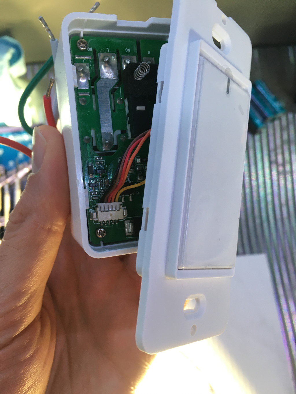
The PCB on the back of the rocker is where the ESP is mounted. Step 2 is to unscrew that board and pull it out. Oh, and I should say, step zero was to disconnect the switch from utility power before doing any of this. You'd think it wouldn't be necessary to write that, but the Tasmota docs have a super obnoxious warning of same alongside a picture of a device that got smoked from what looks like some serious arcing. So someone somewhere apparently tried all this while the thing was still wired to mains power. 😮
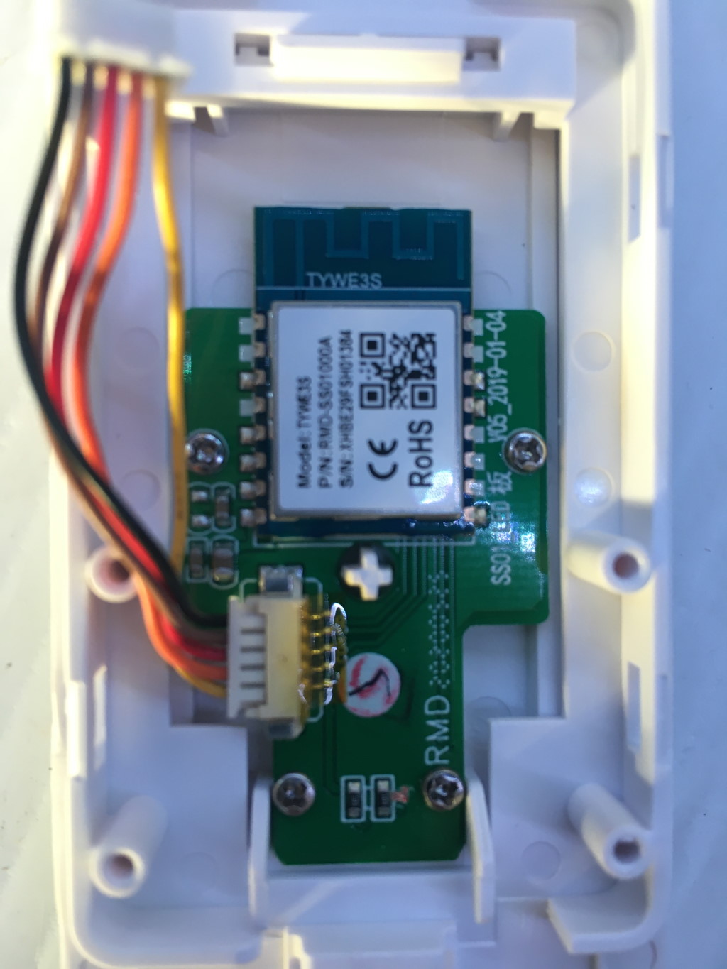
With the PCB-mounted ESP8266 on my bench, I could start to wire it up for
flashing. If you look closely at the ceramic WiFi antenna, the Tuya model
number is printed there: TWYE3S. Tuya has a
datasheet
for this module on their web site which includes the pinout for the ESP.
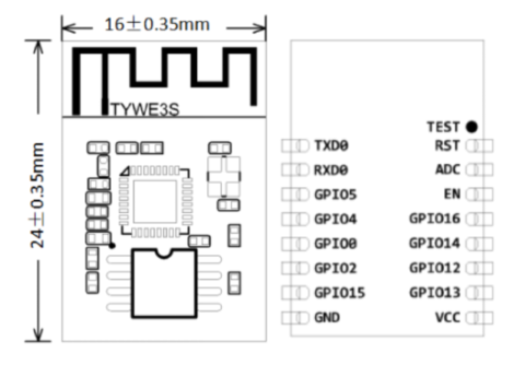
Hopefully this next sentence saves you a bunch of time that I ended up wasting:
the image on the right showing the pins is the under side of the ESP.
If you're looking at the top of the ESP (i.e., you see the TYWE3S label),
VCC is on the left, TXD0 is on the right, and so on.
Others have taken the approach of soldering wires right to the ESP. I've got the tools but not the skill to do such precise soldering so I went a different route. I grabbed some dupont cables with aligator clips and used them to clip onto the ESP.
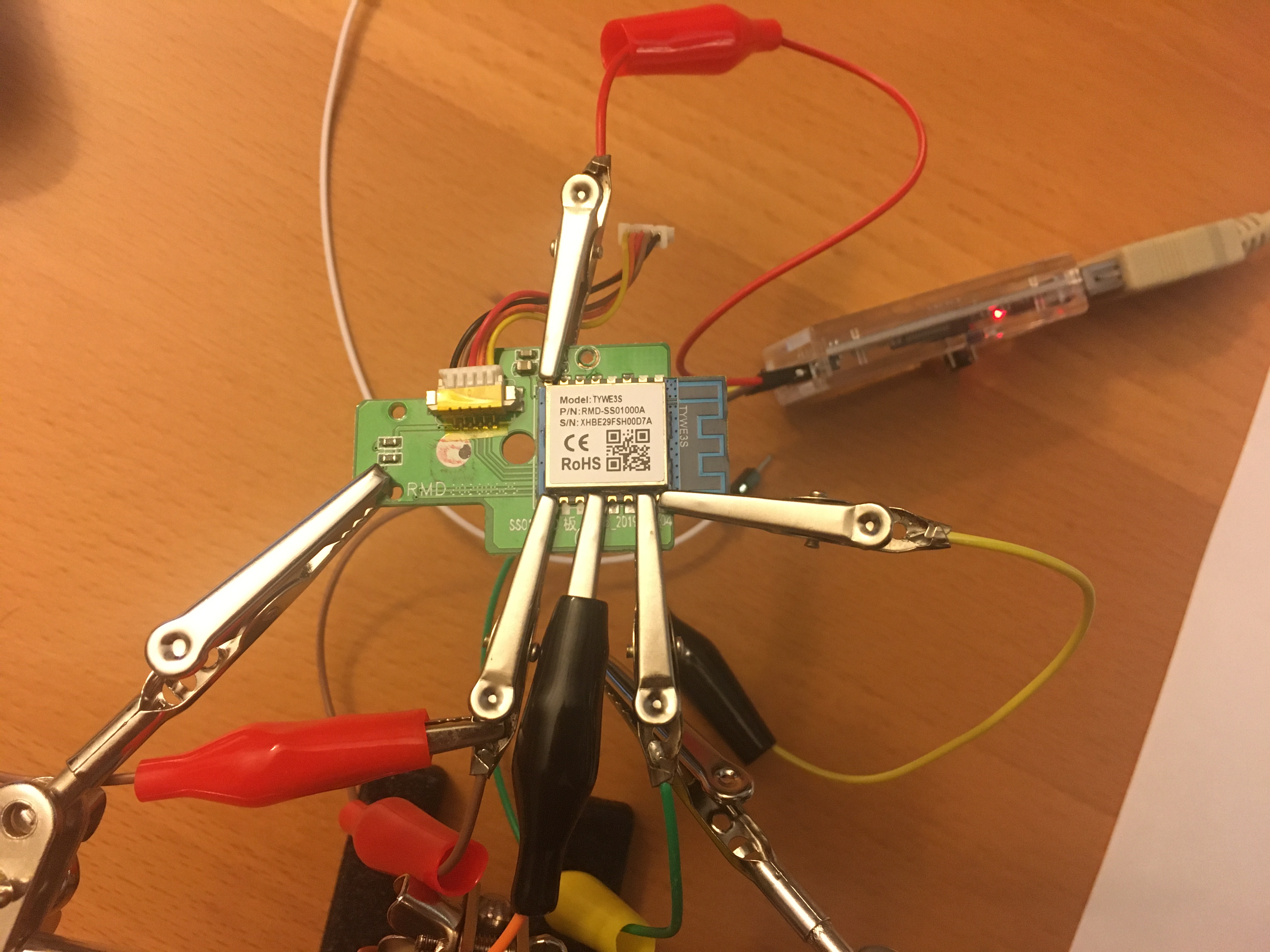
This worked decently well. My biggest concern was one of the clips breaking contact right in the middle of the upload. I was careful not to bump the desk or touch any wires while the flashing was happening.
Next is wiring these cables to the computer. I used a USB to TTL adapter for this. Because I was wiring the ESP to this adapter for comms and power, I made sure to set the adapter to 3V by adjusting the jumper. I then connected the dupont cables to the adapter pins.
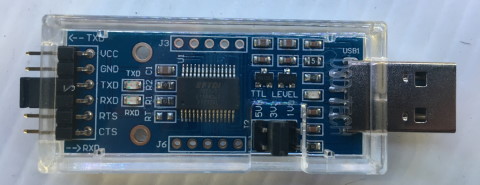
- Adapter
VCCto ESPVCC - Adapter
GNDto ESPGND - Adapter
TXDto ESPRXD0 - Adapter
RXDto ESPTXD0
Last, but not least, GPIO0 needs to be grounded out while the ESP is powered
on to put it into "flash me!" mode. I did this by connecting a male and female
aligator wire back-to-back and then clipping between GPIO0 and the clip I
had already put on the GND pin (that's the clip with the red insulator in the
lower-left of the picture above).
With that done, I plugged in the USB adapter, fired up Tasmotizer which is a simple GUI for flashing ESPs, and let it rip.
I have to admit that this didn't always work on my first crack. Tasmotizer
will time out if something isn't right with the connections. I would unplug,
reposition the clips using the magnifier to ensure I wasn't shorting out to
anything, and try again. One thing I noticed is that it's very easy to short
out the VCC clip to the components on the PCB that are near that pin. When
I took extra care with that clip, I had more success.
Parts⌗
Links to the parts I mention in this post: